

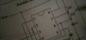
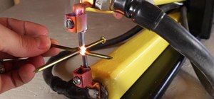
This demonstrates how to wire a 555 timer chip for Pulse Width Modulation. Items used: solderless breadboard, 555 chip, 510 ohm resistor, 100k ohm variable resistor, 1 RGB LED at 20-25ma, wires, and 9v battery. And those vertical lines are what i mean in terms of what you can see only on the camera. You can see the led light of course without the camera.
Just updated your iPhone? You'll find new emoji, enhanced security, podcast transcripts, Apple Cash virtual numbers, and other useful features. There are even new additions hidden within Safari. Find out what's new and changed on your iPhone with the iOS 17.4 update.


1 Comment
If your still around, I have a Question... Here's what I want to do, Our Dog is Trained to Ring the Bells we have hanging on the door handle leading to the Back yard.
I would like to Make something using something like this, that I could activate, Say a LED when the Dog goes up to the Bell and taps it. The trick is I want the LED to be a Remote using RF that I can take it BlueTooth Range distance, I think thats 33'. I have a bunch of Parallax stuff I could use if needed... Or I can buy whatever, I just want the whatever to be a bunch of parts such as, Microchips, resistors, Capacitors, Diodes, and so on. It's a Heck of a lot more FUN to make it than Buy it!!!
Any Suggestions? A thought of mine, I have a couple of BlueTooth headsets lying around broke or the battery is no good in them anymore but still work, Maybe I could make something that has the 555 chip that connects to a Pezio buzzer but instead of the buzzer make it activate a RF signal to the Bluetooth receiver and that turns on an LED and maybe it emits a Sound.... Instead of an LED that activates incorporate it in my home Lighting, so when the dog bumps the bell/Switch it Flickers the lights 1 to 6 times or Dims the lights while flashing a small LED mounted on the Light Switch in each room... That would be pretty Slick!
Share Your Thoughts